Archive for the ‘Arduino’ Category

First Bot Part 02

Posted: August 14, 2012 in Arduino

So here is the working version of the robot, I will talk through some of the steps that stopped the bot from working in part 01.

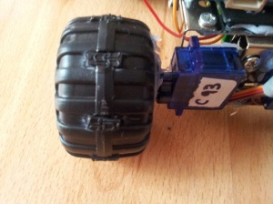
As the wheels are plastic, and my house is all tiles and laminate, the wheels would just spin. Because the Bot uses differential steering grip is a must, as it wouldn’t turn enough.   Rather than replace the wheels all together I cut strips out and then, added in little pieces of rubber.  Not perfect, but MUCH better.

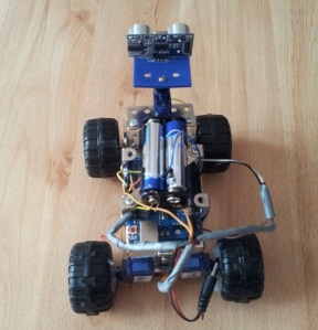
The main problem for my bot was power, the 9v that I had mounted on the breadboard up top wasn’t enough. So went on ebay and got a few 4 battery pack adapters. As these are fairly bulky I didn’t want to add this on top of the 9v, which I kept to power the Arduino. So I moved the 9v to under the bot, got rid of the breadboard, and have just the battery pack up top now.

I glued the head servo to a metal bracket, and cut a piece of plastic for the ultrasonic sensor. The pins of the sensor feed through the plastic, as there was much to attach this to.

Couple of pics below to see what the bot looks like now, taped a few wires as they kept being caught on the wheels.

Just so you can see a size comparison of my Bot, Smudge my cat decided to get in on the camera action.

VIDEO   —-   I will create and upload video in next day or so, just need to tweak code more, then upload that also.
First Bot Part 01

Posted: August 14, 2012 in Arduino

So I went round a few shops looking for parts. I didn’t want to spend more than £10 for a toy that I was just going to rip to pieces for parts.

Then I found the below for £6.99 and £2.99…


Lets see what I did with these 🙂

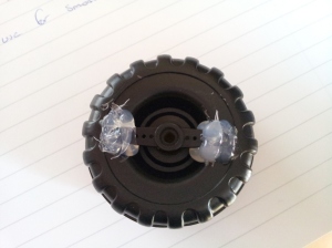
As you can see from the below, this was the way I attached the Servo horn to the wheels. Good old glue gun. **Things to note, first attempt popped off straight away, due to the ultra smooth plastic wheel. I sanded the area down and this gave better results.***

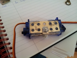
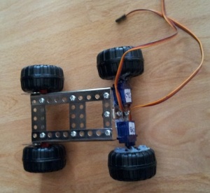
Made a basic bracket for the servos to sit on, then used glue gun to attach them. (dunno if this was  a good idea, could be a night mare if i want to use them elsewhere.

Rear wheels complete.

Was getting a little excited at this point, seeing it starting to come together. Front wheels are held together with a small bar that came with the set.

I wanted the Arduino to be in its own little section, so firstly I put a strip of plastic down this was then held in place with bluetac. I then added another metal strutt above so this would then hold the battery and breadboard. The head servo and ultrasonic sensor was added at this point. As you can see I used bluetac to help me work out where I would have pieces. Bluetac is good but only for static pieces, the amount of times the head(ultrasonic sensor) fell off was unbelievable.

Below was the finished build, that would enable me to test code…   I had a few mistakes at this point.

  • Bluetac to hold head servo
  • The wheels are made of plastic, so just spin on laminate flooring.
  • and most embarrasingly, thinking I could power this with a 9V battery.

See next posts for newer version, which has the above problems ironed out.

Knight rider LED’s

Posted: August 2, 2012 in Arduino

Saw a robot with leds on its head doing the knight rider sequence. I thought this looked pretty cool, and maybe I’ll eventually do it on mine.

First things first lets have a play. As you can see from the first video, I just turned 1 LED on then off then the next LED on. This doesn’t work, as you don’t get  a flow to it.

Now take a look at my second attempt. This was done by turning  LED1 on then turn on LED2 then turn off LED1 before turning LED3 on. Its not perfect, but shows a bit of flow and looks a lot better.

Due to work, and family I don’t get lots of time to work on code, so it will be messy and I’m sure can me made a lot smaller. Something for me to look into. Here’s the code I made for the second video.

int led1 = 8;
int led2 = 9;
int led3 = 10;
int led4 = 11;
int led5 = 12;
int led6 = 13;
int time = 100;
int time2 = 50;

void setup() {

pinMode(led1,OUTPUT);
pinMode(led2,OUTPUT);
pinMode(led3,OUTPUT);
pinMode(led4,OUTPUT);
pinMode(led5,OUTPUT);
pinMode(led6,OUTPUT);
}

void loop() {

digitalWrite(led1, HIGH);
delay(time);
digitalWrite(led2, HIGH);
delay(time2);

digitalWrite(led1, LOW);
delay(time);
digitalWrite(led3, HIGH);
delay(time2);

digitalWrite(led2, LOW);
delay(time);
digitalWrite(led4, HIGH);
delay(time2);

digitalWrite(led3, LOW);
delay(time);
digitalWrite(led5, HIGH);
delay(time2);

digitalWrite(led4, LOW);
delay(time);
digitalWrite(led6, HIGH);
delay(time2);

digitalWrite(led5, LOW);
delay(time);
digitalWrite(led6, LOW);
delay(time2);

digitalWrite(led5, HIGH);
delay(time);
digitalWrite(led4, HIGH);
delay(time2);

digitalWrite(led5, LOW);
delay(time);
digitalWrite(led3, HIGH);
delay(time2);

digitalWrite(led4, LOW);
delay(time);
digitalWrite(led2, HIGH);
delay(time2);

digitalWrite(led3, LOW);
delay(time);
digitalWrite(led2, LOW);
delay(time2);
}

Arduino – Object Avoidance Code

Posted: July 31, 2012 in Arduino

Below is the latest code, which should basically have the bot travel forward until the HC-SR04 detects an object at 10cm or closer. then the servo which the HC-SR04 will look left then right, calculate distance for both directions and turn in the direction where the distance is further to an object. Its based on the Turtleduino project over at indistructables, but he used a PING sensor instead of the cheapy HC-SR04.

Sorry no video for this one, just waiting to collect some parts so we can see it properly in action rather than just on the breadboard.

#include <Ultrasonic.h>
#include <Servo.h>

Ultrasonic ultrasonic(12,13);

const int RForward = 0;
const int RBackward = 180;
const int LForward = 180;
const int LBackward = 0;
const int RNeutral = 91;
const int LNeutral = 92; //constants for motor speed

const int TrigPin = 12;
const int EchoPin = 13;  //Echo pin

const int dangerThresh = 10; //threshold for obstacles (in cm)
int leftDistance = 0;
int rightDistance = 0; //distances on either side

Servo HeadServo;
Servo LeftServo;
Servo RightServo; //declare servos

long duration; //time it takes to recieve ECHO))) signal

void setup()
{
pinMode(TrigPin, OUTPUT);
pinMode(EchoPin, INPUT);
RightServo.attach(11);
LeftServo.attach(10);
HeadServo.attach(6); //attach servo to proper pins
HeadServo.write(90); //centre head servo
}

void loop()
{

int distanceFwd = (ultrasonic.Ranging(CM));

Serial.begin( 9600 );
Serial.print( ultrasonic.Ranging(CM) );
Serial.println( “cm” );
delay(500);

if (distanceFwd>dangerThresh) //if path is clear

{
LeftServo.write(LForward);
RightServo.write(RForward); //move forward
}
else //if path is blocked
{
LeftServo.write(LNeutral);
RightServo.write(RNeutral);
HeadServo.write(0);
delay(500);
rightDistance = ultrasonic.Ranging(CM); //scan to the right
delay(500);
HeadServo.write(180);
delay(700);
leftDistance = ultrasonic.Ranging(CM); //scan to the left
delay(500);
HeadServo.write(90); //return to center
delay(100);
compareDistance();
}

}

void compareDistance()
{
if (leftDistance>rightDistance) //if left is less obstructed
{
LeftServo.write(LBackward);
RightServo.write(RForward); //turn left
delay(2000);
}
else if (rightDistance>leftDistance) //if right is less obstructed
{
LeftServo.write(LForward);
RightServo.write(RBackward); //turn right
delay(2000);
}
else //if they are equally obstructed
{
LeftServo.write(LForward);
RightServo.write(RBackward); //turn 180 degrees
delay(2000);
}
}

long ping()
{
// Send out PING))) signal pulse
pinMode(TrigPin, OUTPUT);
digitalWrite(TrigPin, LOW);
delayMicroseconds(2);
digitalWrite(TrigPin, HIGH);
delayMicroseconds(5);
digitalWrite(TrigPin, LOW);

//Get duration it takes to receive echo
pinMode(TrigPin, INPUT);
duration = pulseIn(TrigPin, HIGH);

//Convert duration into distance
return duration / 29 / 2;
}

Below is the code for finding the stalling point of a servo. All seem to be different, even though I bought a batch of all the same servos the stalling positions are different. ie one is 93 and another is 91.

not the best video in the world, but you can see and hear the motor slow down then stop at value 93


// Includes
#include <Servo.h>

// Define global constants
#define lServoPin 9   // Left motor pin; This is a special PWN pin

// Define global servos
Servo LeftServo;

// Initialization function
void setup()
{
// Initialize server connections
LeftServo.attach(lServoPin);

// Initialize serial communications
Serial.begin(9600);
}

// Main loop
void loop()
{
// Set both servo at same speeds (Go straight)
for(int i = 0; i <= 180; i++)
{
LeftServo.write(i);
Serial.print(“Value: “);
Serial.print(i, DEC);
Serial.print(“\n”);
delay(500);
}
}

So I bought a couple hxt9g servos, and have modded them for continuous rotation. The reason behind this was I’m still learning a lot when it comes to Arduino. There are Sheilds and H-bridges when using motors, so hacking a servo is an easy way around this from what I’ve been reading.

below code is not mine, but enables you to use the < > keys to control direction and speed.

/*
* Serial Port Continuous Rotation Servo – Movement and Speed Control
* ————–
*
* Alteration of the control interface to use < and > keys
* to slew the servo horn left and right.  Works best with
* the Linux/Mac terminal “screen” program.
*
* Adapted for Continuous Rotation Servo (Parallax)
* by Orfeus (for http://www.grobot.gr)
* v.200910211932
*
* For Serial Port Terminal on Windows I used PuTTY SSH Client
* ( freeware at http://www.chiark.greenend.org.uk/~sgtatham/putty/download.html )
*
*
*
*
* Created 10 December 2007
* copyleft 2007 Brian D. Wendt
* http://principialabs.com/
*
* Adapted from code by Tom Igoe
* http://itp.nyu.edu/physcomp/Labs/Servo
*
*/

/** Adjust these values for your servo and setup, if necessary **/
int servoPin     =  9;    // control pin for servo motor
int minPulse     =  1170;  // maximum servo speed clockwise
int maxPulse     =  1770; // maximum servo speed anticlockwise
int turnRate     =  75;  // servo turn rate increment (larger value, faster rate)
int refreshTime  =  20;   // time (ms) between pulses (50Hz)

/** The Arduino will calculate these values for you **/
int centerServo;         // center servo position
int pulseWidth;          // servo pulse width
int moveServo;           // raw user input
long lastPulse   = 0;    // recorded time (ms) of the last pulse

,
void setup() {
pinMode(servoPin, OUTPUT);  // Set servo pin as an output pin
centerServo = maxPulse – ((maxPulse – minPulse)/2);
pulseWidth = centerServo;   // Give the servo a stop command
Serial.begin(9600);
Serial.println(“Arduino Serial Continuous Rotation Servo Control”);
Serial.println(”          by Orfeus for GRobot.gr”);
Serial.println(”   Press < or > to move, spacebar to center”);
Serial.println();
}

void loop() {
// wait for serial input
if (Serial.available() > 0) {
// read the incoming byte:
moveServo = Serial.read();

// ASCII ‘<‘ is 44, ASCII ‘>’ is 46 (comma and period, really)
if (moveServo == 44) { pulseWidth = pulseWidth + turnRate; }
if (moveServo == 46) { pulseWidth = pulseWidth – turnRate; }
if (moveServo == 32) { pulseWidth = centerServo; }

// stop servo pulse at min and max
if (pulseWidth > maxPulse) { pulseWidth = maxPulse; }
if (pulseWidth < minPulse) { pulseWidth = minPulse; }

// Show me the keys I pressed
//Serial.print(“Key pressed: “);
//Serial.println(moveServo);

//print pulseWidth back to the Serial Monitor (comment to undebug)
Serial.print(“Pulse Width: “);
Serial.print(pulseWidth);
Serial.println(“us”);
}

// pulse the servo every 20 ms (refreshTime) with current pulseWidth
// this will hold the servo’s rotation and speed till we told it to do something else.
if (millis() – lastPulse >= refreshTime) {
digitalWrite(servoPin, HIGH);   // start the pulse
delayMicroseconds(pulseWidth);  // pulse width
digitalWrite(servoPin, LOW);    // stop the pulse
lastPulse = millis();           // save the time of the last pulse
}
}

/* Orfeus 200910212001 */

Lets make it a nice and simple one…

So I’ve just picked up the Arduino UNO, and a LCD/Distance sensor kit. I don’t know too much about programming and electronics, but I got this up and running without too much hassle. Vid links below.

Code, which also includes a bit of code that outputs cm to serial as well as LCD and will say out of range when more than 100cm.

#include <Ultrasonic.h>
#include <LiquidCrystal.h>

LiquidCrystal lcd(12, 11, 5, 4, 3, 2);
Ultrasonic ultrasonic(7,6);

void setup()
{
Serial.begin( 9600 );
lcd.begin(16, 2);
lcd.print(“Testing…”);
}
void loop()
{

if (ultrasonic.Ranging(CM)>= 100) {
Serial.println(“Out Of Range”);

}
else {
Serial.print( ultrasonic.Ranging(CM) );
Serial.println( “cm” );
}
delay(1000);

lcd.clear();
lcd.setCursor(0, 0);
lcd.print(ultrasonic.Ranging(CM));
lcd.print(“cm”);
delay(100);
}